


We want to keep you in the loop! Our website is currently undergoing some exciting enhancements to provide you with an even better online experience.
JMAG was developed over more than 30 years to solve the complex magnetic, thermal and structural analysis problems in different technology areas. It is an efficient tool for designing the power transformer, converters and wireless power transfers. Whereas the determination of transformer parameters, impedance, winding hot spots temperature, insulation effects, defaults, etc. are the major challenges while designing these kings of electric machines. It also enables the visualization of the phenomena and ease in moving forward with analyzing causes. It also makes possible quantitative evaluations of temperature rising inside objects or noise where measurement is difficult.
From geometry modelling of power transformer components, model setup, and material modelling to high mesh quality generation, insulation, transformer cooling, design integration, vibration and acoustic noise, this comprehensive software give more accurate solutions on variety of investigations that are possible in the power converter design. JMAG can simulate both winding and iron losses including the harmonic effects of the drive circuit. Generally, it can be used for example, to design and optimize:
The studies for Linear/Rotative motors that can be solved by JMAG are:
2D/3D Magnetic Field Analysis (Static, Transient, Frequency)
2D/3D Iron Loss Analysis (Transient, Frequency)
2D/3D Thermal Analysis (Static, Transient)
2D/3D Structural Analysis (Static, Eigenmode, Transient, Frequency)
3D Electric Field Analysis (Static, Frequency, Current distribution)
2D/3D Thermal Stress Analysis (Static, Transient)
2D/3D Transformer Analysis (Static, Transient, Frequency)
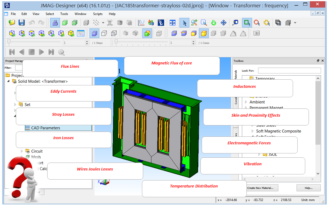
Some examples of the results obtained after performing these analyses are listed below:
Magnetic flux, Magnetic field, Magnetization, Flux linkage, Voltage, Current, Electromagnetic force, Lorentz force, Magnetostriction force, Inductances, Resistances, Permeability, Stored energy, Joule losses, Hysteresis losses, Iron losses, Dielectric losses, Electric field, Electric potential, Electric Charge, Electric power, Vector potential, Temperature, Heat flux, Heat flow, Heat source, Thermal resistance, Electric potential, Displacement, Deformation, Velocity, Acceleration, Stress, Strain, Sound pressure and Sound Pressure level.
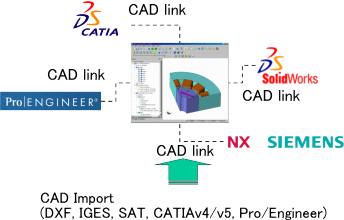
JMAG-Designer has many tools with different methods to create and import CAD geometry of the Power Converters and Transfers.
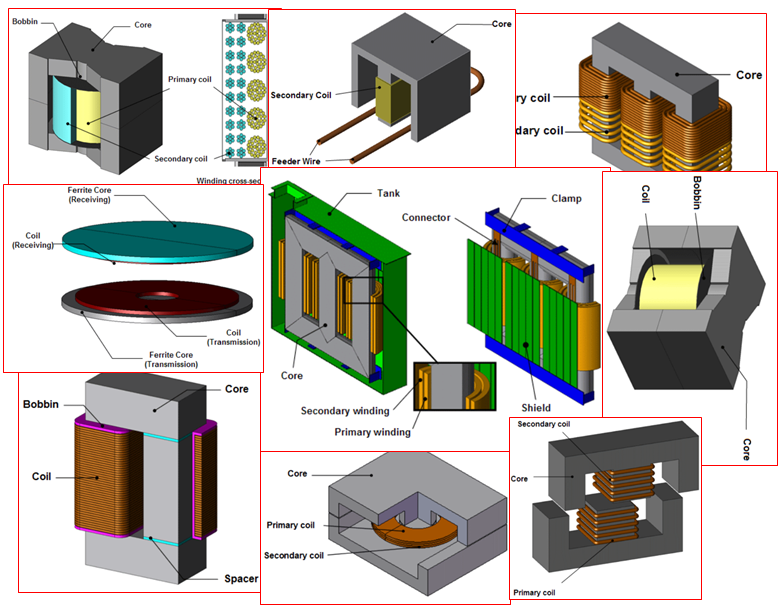
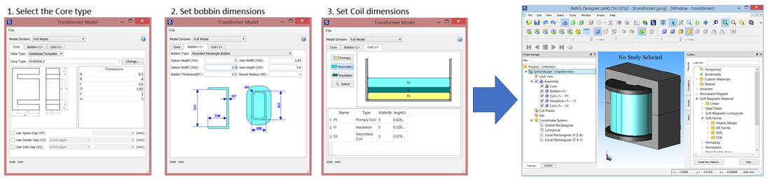
JMAG's transformer template tool has geometry templates of transformers and inductors that are often used. The model geometry can be created by simply specifying the dimensions. Geometry from the TDK core catalog is built into the database so that our users can model core geometry simply by selecting what they need. The bobbin geometry and the coil arrangement are also specified easily using templates. Users that want to investigate core geometries with characteristics that cannot be expressed by the existing templates can use features for importing CAD models.
Highly customizable mesh can be generated with higher quality. the Automatic Mesh feature recognizes any model geometry and automatically generates a high-quality mesh over the entire model including the surrounding air region and air gaps. The adaptive mesh feature uses simulation results to control the mesh size to provide a more optimal mesh.
The flux lines for losses caused by the proximity and skin effects are a vital aspect of the power converters and transfer analysis. Therefore, a specialized mesh and analysis functions has been developed. This innovation allows an analysis for example, to account for effects of litz wire swiftly, which was very difficult to include up until now. Some example of mesh functions are described below:
The key to analysis accuracy depends on whether an analysis is run using the right material properties. An analysis performed with the most detailed model will not obtain accurate results if the wrong material properties are used. Catalog data from TDK, JFE, and Hitachi Metals are included in the JMAG material database offering ferrite that is often used for high frequency transformers.
Catalog data from Sumitomo Metals, Nippon Steel, JFE, and China Steel are also included for the material properties of magnetic steel so that analysis accounting for nonlinear characteristics of the material properties can be performed. In addition, material properties for iron loss characteristics and stress dependency for each manufacturer are included in addition to the BH curves to increase the analysis accuracy. The material properties can be set just like conditions by simply selecting a material from the material database and dragging and dropping the material on the model in the graphics window.
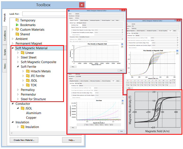
We can run the FEA simulation by using any electromagnetic steel sheet materials taking to account their Anisotropic or Isotropic behaviors with the following properties:
The lamination steel sheet properties such as lamination direction, lamination factor, lamination thickness and saturation factor can be also accounted into the simulation.
JMAG's transformer analysis is a specialized magnetic field analysis for evaluating transformers and inductors. The procedures necessary to perform an analysis from creating the model to evaluating the analysis results have been dramatically simplified by limiting the analysis target to transformers based on the reputable features of JMAG's magnetic field analysis. The geometry and conditions that can quickly become complicated can now be created and specified easily. Transformer designers who are unfamiliar with CAE simulations can perform highly accurate analysis right after JMAG is implemented by using JMAG's transformer analysis.
The results obtained from a transformer analysis can be easily used to implemented coupled analysis with the thermal analysis solver and structural analysis solver available in JMAG. Loss distributions caused by copper loss accounting for the high frequency current distribution of the coil as well as iron loss that has varying degrees of magnetic flux distribution in the core can be captured accurately. A thermal analysis that accounts for the effects of heat dissipation can be performed in addition to obtaining vibration and noise using a structural analysis that accounts for the electromagnetic force produced in each part. JMAG is simple when performing multiphysics analyses encompassing the complicated physical phenomena that makes CAE simulations superior.
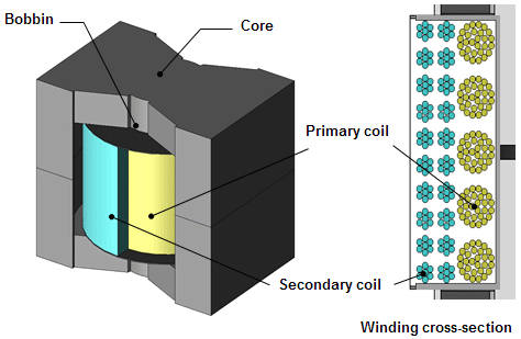
Flyback converters are used for various applications such as power supply circuits, which is suitable for small electrical power that realizes switching power supply. Since there are not many parts and it is a very simple structure but sometimes they contain some complex winding modelling with the Litz wires.
The Litz wire is one wire separated into multiple thin wires, painted with enamel film, and twisted together. Separating one wire into multiple thin wires controls the concentration of current due to the skin effect. By adding twisted structure to the bundle wire, it is expected that the current flows more evenly, and local heat generation is controlled.
JMAG allows the accuracy evaluation of Litz wire by using transformer analysis module. So, for example, we can confirm the effects on copper loss due to the presence or absence of a twisted structure in the winding regarding the copper loss that occurs in the small switching transformer structured with PQ cores.
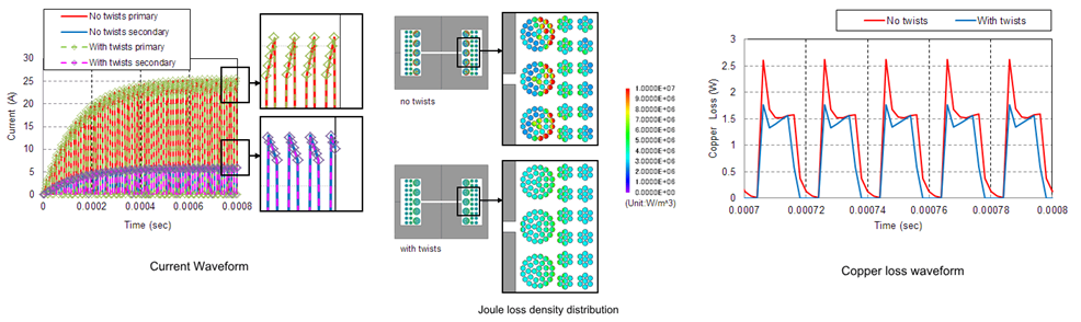
Higher and higher frequencies are being used for the drive frequency in small-scale power transformers in order to reduce their size even more. These higher frequencies lead to problems such as increased loss and localized heat generation because of skin effects and proximity effects in the windings. In order to reduce loss and localized heat generation, the use of litz wire has increased, and therefore so has the need for analysis that accounts for litz wire.
The number of litz wires per bundle that can be used and the solving speed in analysis within transformer studies have been greatly increased. It is not unusual for the number of strands in a litz wire bundle to be more than 100, but investigation using transformer studies is made possible by the great increase in calculating ability.
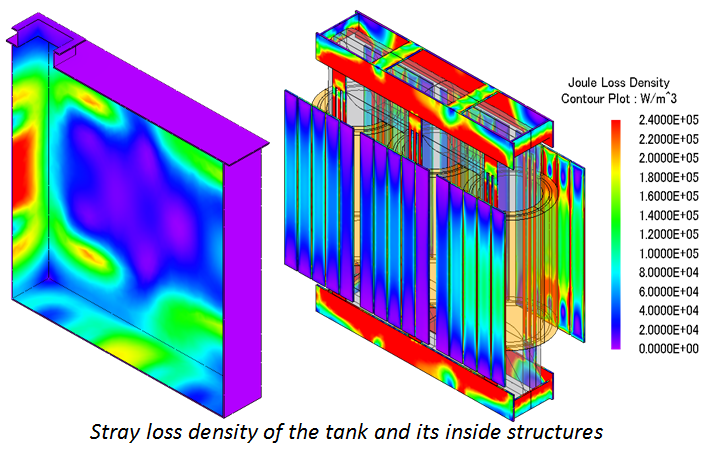
Localized heating due to stray losses affect the transformer’s insulation and insulation oil. This causes dielectric strength to deteriorate
Predicting stray loss distribution requires a magnetic field analysis. Magnetic field analysis allows designers to model the transformer and its surrounding components to better determine how stray losses are affecting the design.
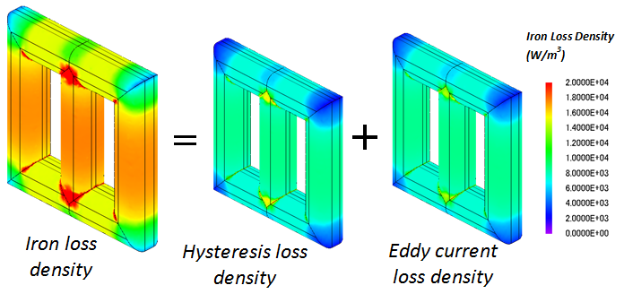
Iron loss is determined by the time variation of magnetic flux density. Anisotropic laminated steel is used as the iron core of transformer.
Thus, in a transformer analysis, the magnetic material properties for the easy axis and hard axis of a core are independently defined. Due to anisotropic effects occurring nearby the joint where leg and yoke parts connect in a V-shape, concentrated iron loss occurs in frame-shaped lamination cores.
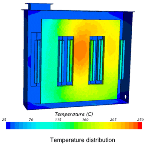
Localize heating is prevented by the cooling effects of the insulation oil.
The coupled analysis of JMAG that evaluates losses as heat sources and thermal CFD makes it possible to confirm the exact temperature distribution of the transformer.
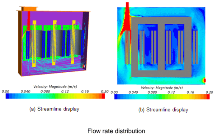
The figure shows the velocity flux distribution of thermal CFD results. The tanks forced convection, causes oil to flow from the bottom of the tank up to the top where it is warmed up and then expelled from upper portion of the tank.
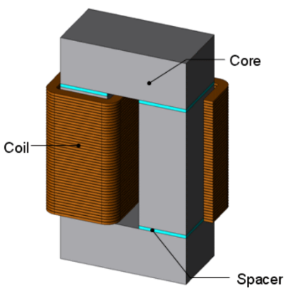
Coil vibration occurs due to phase differences between the primary and secondary coils. This phase difference causes strong repulsion between the coil’s and induces vibration. The mode shape of vibration is strongly dependent on the coil’s winding pattern. For example, in transformers with cylindrical shaped coils, elliptical vibration modes occur, causing noise.
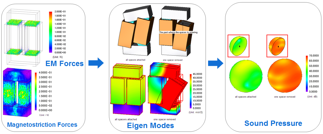
Excitation noise is caused by magnetostriction and magnetic attractive forces near the joints of cores. In this particular case, we paid our attention to excitation noise due to magnetostriction. By defining the magnetostriction properties of the core, we obtained the vibration/noise cause by magnetostriction distribution. We were also able to obtain the magnetostriction distribution itself from magnetic flux density distribution.
In addition to normal power conversion, a transformer’s insulation structure has to be designed to be able to withstand lightning strikes and excess voltage during short circuits.
The dielectric strength of a transformer is mainly determined by the insulation oil.
The vicinity of the press board of the high-voltage side winding is an area where localized high electric field tends to occur. The electric field analysis forecasts whether the localized electric field does not exceed the insulation limit.
Inrush currents are caused when power is turned on and results in excessive compressive forces on the winding due to the Lorentz force which arises in a coil is so large that it is possible to observe coil deformation. This compressive force is.
The software JMAG is developed by JSOL Corporation and distributed in Europe and USA by Powersys.
JMAG is simulation software developed by the JSOL Corporation for the design and development of electrical equipment’s.
Today, numerical methods are increasingly used for the solution of electromagnetic fields and there is a variety of commercial computer programs based on the finite element method (FEM) used for electric machine design. JMAG are dedicated tool for this king of purpose, it’s useful during the FEA simulation and optimization process of an electrical machine because it provides more advanced methods to assess more accurately the final optimal characteristics of the design. This innovative software offers very suitable solutions for motor designers, engineers, and manufacturers, as well as graduate students, and academic researchers, and it covers the design and design-related issues, modeling and simulation, engineering studies, testing process, and performance characteristics of electric machines.